Virtual Build
Virtual Build Feature Overview
•New Assembly Planner Module for viewing parts and components in a 3D visual graphical representation
•Consumption mapped to activities can be viewed in a sequential build order – Virtual Build
•Provides feedback to viability to assembly processes along with build order verification
•Image capture, annotation, and work step functionality to aid SOP (work instruction) generation
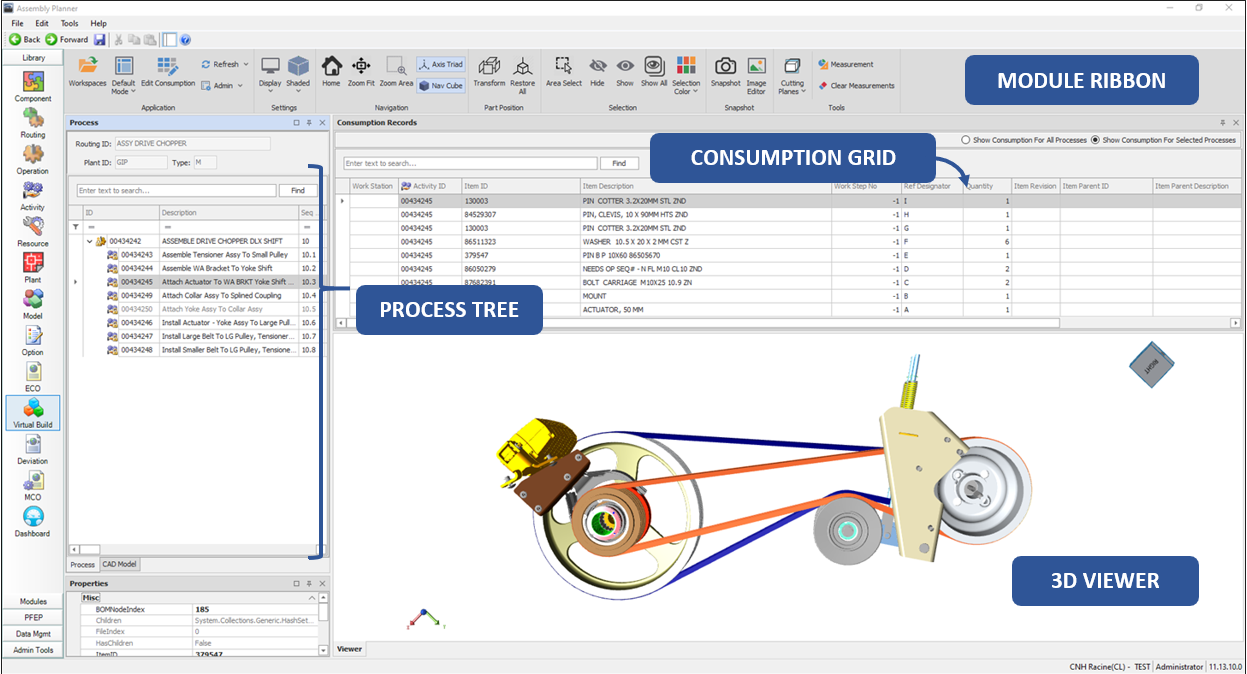
Process Tree
•Indicates information about the currently selected processes; Routing, Operations, Activities
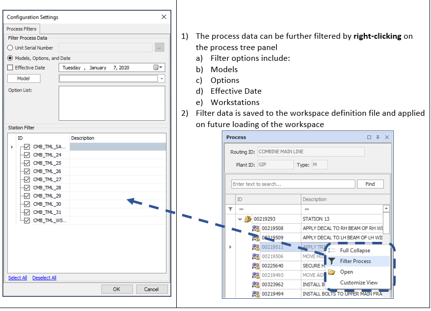
•Filtering capabilities allow the user to filter processes by date, models, options, and workstations
•Above filter selections are simultaneously applied to the consumption and 3D views
•Activities assigned to Operation are displayed in a tree format; allows for customizable views
Consumption Grid
•Displays consumption mapped to the selected process(es)
•Information fields also include routing, operation, and activity data with the ability to customize the view
•Consumption data is simultaneously filtered with process data as noted above
•Consumption grid is detachable to move to a secondary screen
•Future Capability: Edit mapped consumption without leaving the Virtual Build Module
3D Viewer
•Panel used to display 3D data specified by the process and consumption selections
•Flexibility to allow for viewing one process and consumption selection or showing a sequential buildup of assemblies as processes are stepped throughHandles many different CAD inputs that are converted to a very lightweight format for ease of maneuverability
Module Ribbon Features
Workspaces
Workspaces contain the definitions for information that will loaded to the Virtual Build Module
The workspace defines the workspace name, applicable routing, assigned CAD files, supporting or additional CAD files, filter information assigned by the user, the person who defined the workspace, and the date the workspace was created or modified
Flexibility to allow for creation of multiple workspace scenarios for same CAD model
Workspace Manager; UI for defining, opening, and editing workspace(s) – More detail below
PRC & HSF files are supported; mixing of formats is not supported in the same workspace

Application Modes
DEFAULT MODE:
Allows simple interaction with process, consumption, and 3D model data
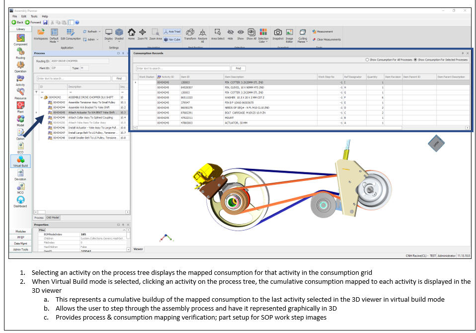
VIRTUAL BUILD MODE:
Selecting Virtual Build Mode allows the user to step through process Activity Sequence No’s
A 3D representation of components mapped as consumption is displayed for the user
A cumulative buildup of the mapped consumption to the last activity selected is displayed
Provides process & consumption mapping verification; part setup for SOP work step images
HIGHLIGHT MODE:
When Highlight Mode is enabled, the parts mapped to the selected activity consumption are highlighted in the 3D viewer
INSTANCE MAPPING MODE:
Allows user to specify with a particular instance of a component is being used with selected activity; useful in cases where multiple quantities exist for a component, but only a subset is used on the selected activity

Mode Options
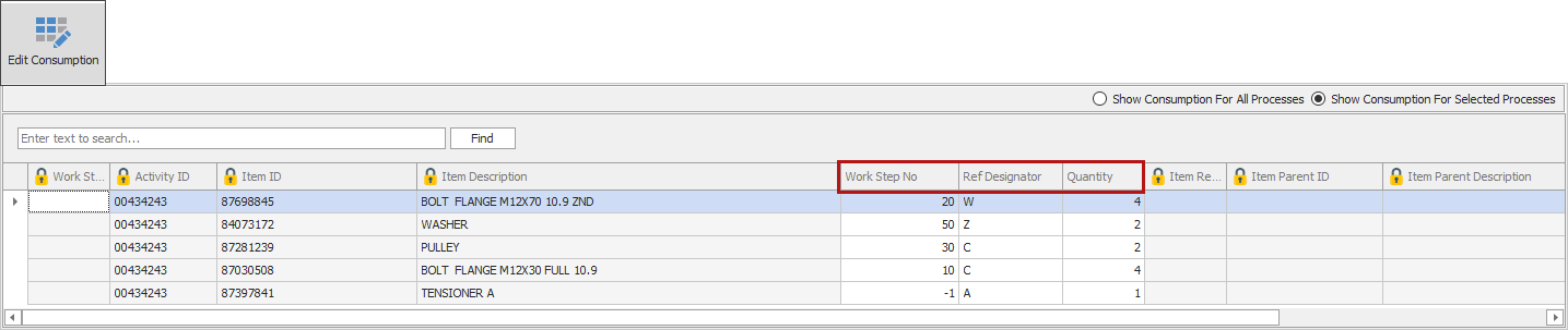
Edit Consumption
While in Default Mode, basic editing of key fields is possible
Fields include: Work Step No, Reference Designator, & Quantity
Refresh Modes
REFRESH:
Refresh of 3D Viewer – not reloading model
REFRESH PROCESS DATA:
Refresh of data in process tree – routing, operations, and activities
FULL REFRESH OF WORKSPACE:
Reloads all 3D model and process data

Refresh Options
Display:
DISPLAY SETTINGS:
Change viewer background color; control of different panel visibility within module

Display Settings
Rendering Modes:
Allows user to set the desired rendering effect of the model displayed in the 3D Viewer

Rendering Options
Home :
![]()
•Smoothly activates the default view for displayed 3D geometry
•Note: the default view is typically assigned during the geometry design phase
Zoom Fit :
![]()
Adjusts the zoom level of the displayed 3D geometry to the center of the 3D viewer region while ensuring that all geometry fits within this region
Zoom Area:
![]()
The user can click and drag the mouse around components in the 3D viewer to perform a zoom based on the specified area
Navigation (NAV) Cube & Axis Triad:
NAVIGATION (NAV) CUBE:
![]()
The 3D geometry can be orientated according to the view selected on the navigation cube face
The navigation cube can be toggled on and off
AXIS TRIAD:
![]()
Allows the user to position the displayed components following the X, Y, & Z axes.
The scene is manipulated by selecting the desired axis to rotate displayed parts in the 3D viewer
The axis triad can be toggled on and off
Transform and Restore All:
TRANSFORM:
![]()
An exploded view of an assembly is generated showing each component of the model separated from the other components
Functionality is useful in showing the relationship or order of assembly of various parts
A selected part can be selected and translated (or moved) from its original position
Double-click the part to view transformation guides
RESTORE ALL:

Restores the part(s) to its original position
Area Select:
![]()
When enabled, functionality is enabled to allow selecting multiple objects in the 3D viewer
Clicking and dragging the mouse creates an overlaid rectangle will be drawn to show the selection area; ultimately highlighting selected parts
Parts are highlighted green or yellow depending on their original color
Hide:
![]()
Allows the hiding of selected component(s) in the 3D viewer by toggling the visibility to off
Show:
![]()
Allows the showing of selected component(s) that were previously hidden in the 3D viewer by toggling the visibility to on
Show All:

The show all command shows all previously hidden components in the 3D viewer to setting their visibility to on
Selection Color:
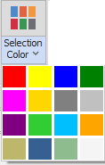
The highlight color of a selected part can be changed
Image Editor:
SNAPSHOT BUTTON:
When coupled with tools above, the user can capture an image of the 3D representation
Once the image is captured, it can be further edited along with saving as a snapshot, adding annotations, or setting as a SOP Image.
Further details covered below
![]()
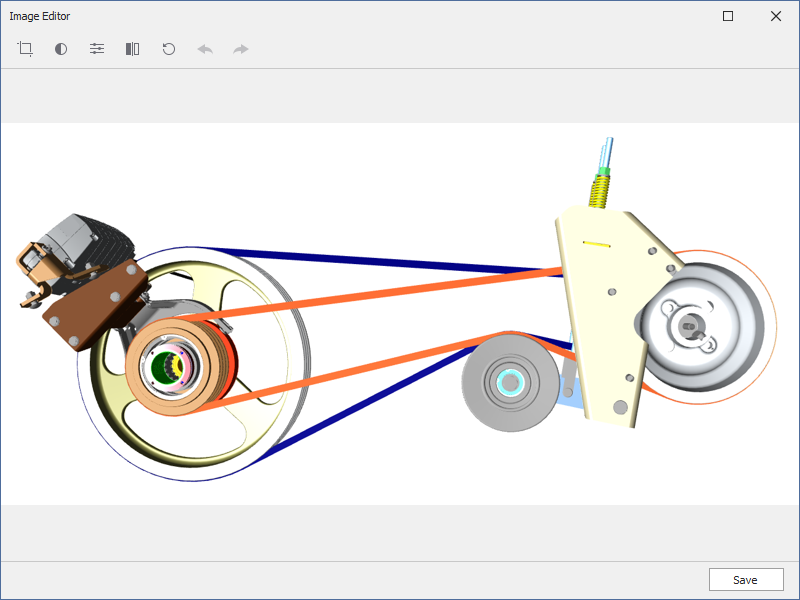
IMAGE EDITOR BUTTON:
Allows editing of images intended to be used as SOP images; discussed in detailed below
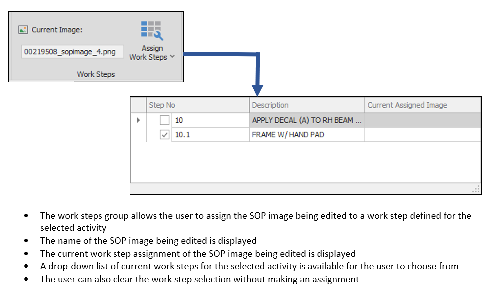
Capability to combine images, annotate images, and assign image to work steps
Note: an activity must be selected on the process tree to use the image editor
![]()
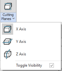
Cutting Planes:
Cutting planes can be inserted into the 3D Viewer area to allow for sectioning of the model
Cutting planes can be inserted along the X, Y, & Z axes
Cutting plane visibility can be toggled on and off
Measure:
![]()
•Allows measuring of distances between desired components
•Measurements can be made by either length, point to point, feature to feature and angle
•Measurements are collected in the model browser; they can be hidden, shown or deleted
•It is possible to hide or show all measurements at once from the Model Browser
Clear:
![]()
•Clear previously made measurements and markups
•When using the clear function, only markups in the active layer are taken into consideration
•Measurements and markups can also be undone while they are being inserted
•The markup or measurement can be removed by pressing ESCAPE
Open Workspace

1)A workspace is opened containing definitions for the specified information.
a)The workspace defines the
Workspace name
Applicable routing
Assigned CAD files
Supporting or additional CAD files
Process filter information assigned by the user
The person who defined the workspace
The date the workspace was created or modified
2)A previously defined workspace can be edited
3)The Workspace Manager contains sort and search features

Workspace Manager
Workspace Editor
![]()
Allows the user to create a new workspace
A current routing is selected for the workspace; selecting includes operations and activities
A base CAD model is assigned to the workspace
Additional CAD models can also be assigned to display concurrently with the base CAD model
Workspace definitions can also be edited by using 

Create Workspace
REQUIRED INFORMATION:
Workspace Name
Routing ID (selected from previously defined Routings)
The preferred CAD file format type can be selected
The base CAD file is selected to the focal point for the workspace
ADDITIONAL CAD (OPTIONAL):
Additional CAD (supplementary) CAD files can be assigned to compliment the base CAD file
Loaded Workspace
CAD Files Loaded:
1)Main CAD and additional CAD file(s) defined in the workspace definition are loaded to 3D viewer
a.Native CAD formats are converted to PRC or HSF format allowing for performance optimization
b.A workspace may define either PRC or HSF formats; however, a mixture of these formats in the same workspace is not currently supported

3D Viewer
Load Process Data:
1)The routing data is retrieved
a.Includes Operations assigned to the Routing ID
b.Includes Activities assigned to Operations discussed above
c.Any process filter data defined in the workspace file is applied to the Operations and Activities list
2)The process data is loaded to the process tree sorted by activity sequence number by default

Process Data
Filter Process Data:
Consumption Data Retrieval:
View CAD Modes
CAD Model View:
•With the CAD Model view, engineers can simply view the CAD Model to visualize, query, measure and snapshot any components or assemblies. Engineers can click on a part number within Assembly Planner’s mBOM or enter a part number and have that component(s) be selected or highlighted in a different color within the CAD Model. This interaction between Assembly Planner and the CAD Model makes manufacturing visualization much quicker, easier and accurate than traditional independent viewers offer.

CAD Model View
Process View:
• The Process View is enabled within a new Workspace Feature which allows the engineer to link a BOP Routing and mBOM to the CAD Model. This workspace enables the engineer to view the Process’s consumption of the mBOM concurrently with the CAD Model as well as reconcile, author and edit this consumption mapping of components to the BOP Routing.
•Reference Designators can even be defined to call out specific Bolts or Items to a specific Process step which consumes them. Using the powerful new Workspace Feature, engineers can now visually associate the Process to the Product to create more accurate process work instructions and assembly sequences during initial launch to the shop floor.

Reference Designator
•Instance mapping feature allows each bolt to be directly reference to a specific Activity or Workstep.
•CAD Models can include components from multiple variants and the engineer can select a specific variant to view and document within the Workspace. The Workspace can also concurrently import multiple CAD models in order to create a combined assembly which might have originally been created from different CAD systems.
•An additional powerful capability of the Workspace is an Item ID Mapping module that allows the engineer to quickly, and easily link Items between the mBOM and CAD Model to resolve common discrepancies with part naming conventions between Engineering, Manufacturing and Operations.

3D Virtual Assembly
•In the Workspace, engineers can navigate the Process according to the assembly sequence by simply selecting stations (operations) or Activities (tasks) in the Process tree on the left. Since all of the components are consumed by the Activities within Assembly Planner’s database, the viewer knows to only display those components assembled so far in the process and thus all other components in the CAD Model are filtered out.
•Users can then decide to automatically color code those active components consumed in the selected Activity and gray out everything else, or to simply highlight active components while showing the consumed components in their default color.
•Engineers can rebalance the Process in Proplanner’s powerful Line Balancing module and apply a balance scenario to the database for immediate visualization, verification and documentation of the task-to-station assignment in the Workspace.
Snapshots & Image Editor
Snapshot Image Capture:
![]()
•Image snapshot allows the user to capture an image from the 3D viewer region
•A preview of the image is displayed, allowing choices for handling the image
•Edit image provides functionality to size, crop, set contrast & brightness before further image handling
•The user can also simply save the image as a snapshot against the selected activity to be used later
•The image can also be saved directly as an SOP image that may be used within the SOP when further editing is not necessary; prompted for work step assignment
•The user also has the choice of directly annotating the snapshot with embellishments to be used as an SOP Image and directly assigned to a work step within the image editor
•The preview can also be discarded by cancelling the snapshot preview

Preview Image
Image Editor Feature Overview
•The redesigned Image Editor acts as a multifunctional tool for working with image documents within the selected activity
•SOP images are easily created from collected snapshots or from importing a desired image file
•Standard and custom shapes are available to aid in the image annotation process
•Previously saved SOP images can be easily edited WITHOUT recreation of the entire image; i.e. – annotations can be added or modified, images can be moved, added, deleted or edited
•Ability to link an SOP images (XML or PNG) can be assigned directly to a workstep from the editor.
•SOP Image XML documents which contain the annotation, image, and textual objects in the work instruction image that is eventually captured as a PNG file.
•Create corporate libraries of annotation symbols, text styles, and color standards which can then be applied to all users within your organization.
Shape Panel:
•The shape panel contains templates, referred to as stencils, that contain shapes used in the image annotation process
•Shapes are added easily by dragging and dropping onto the image editing workspace
•Assembly Planner contains standard annotation shapes and standard assembly icons; customizable border properties, font types, and fill properties can be set as an administration level function or at the user session level
•Additional custom annotation shapes and assembly icons can be added to meet the unique needs of the customer or business case

Shapes
Image Galleries:

Snapshot Gallery

SOP Image Gallery
•To aid with organization, two types of image galleries exist for the selected activity in the virtual build module
•The Snapshot Gallery contains the snapshots that have been collected and stored for the specified activity. The Snapshot Gallery is a simple collection of gathered images to be used in SOP Image generation.
•The SOP Image Gallery contains all created SOP Images for the selected activity. The SOP Image Gallery contains a collection of images that have received some level of image authoring and are intended be used in activity SOP materials.
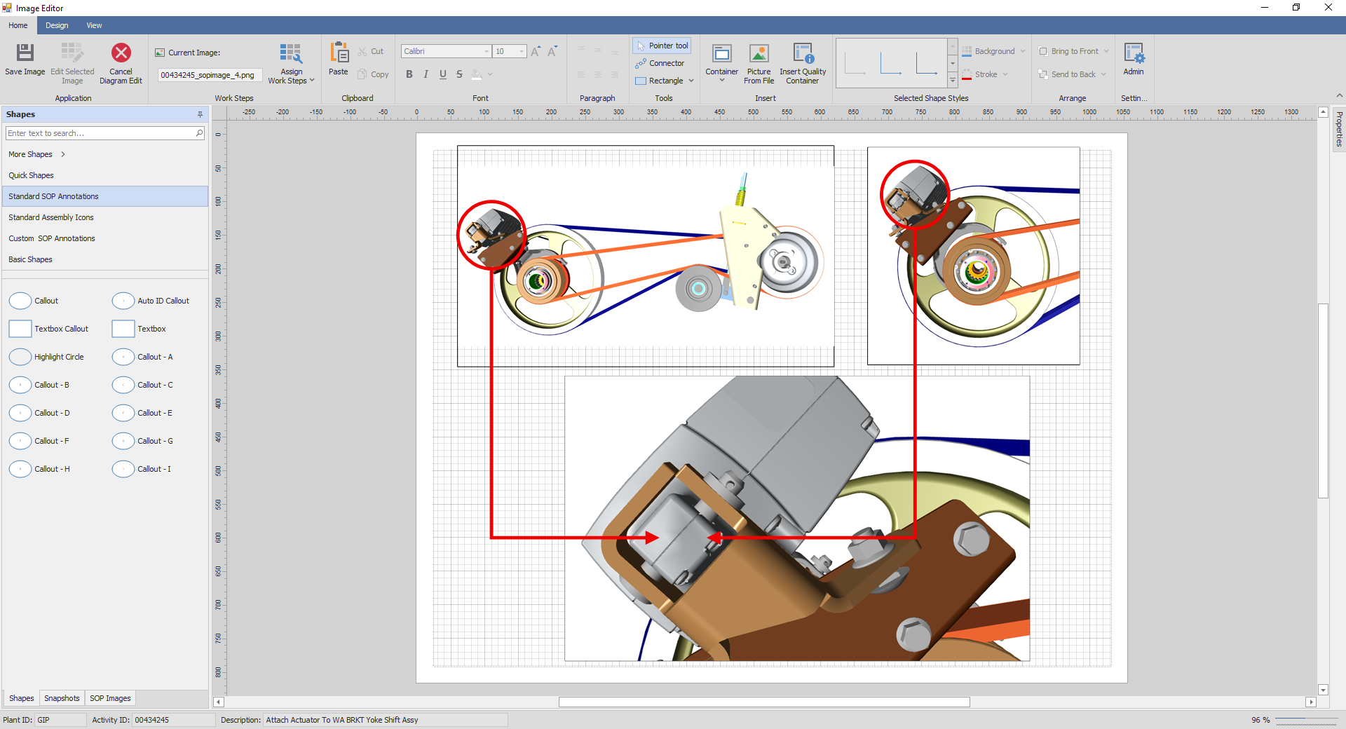
Image Editing Workspace
•The Image Editing Workspace is the central authoring point for creating SOP Images within the Assembly Planner Image Editor
•Snapshot images can be dragged and dropped onto the workspace
•Shapes and icons can also be dragged and dropped into a desired location within the workspace
•After dropping an image onto the workspace, image can be edited as desired for size, crop, contrast, and brightness
•In addition to snapshots, images can also be directly imported into the Image Editor Workspace
•All created and saved images are fully modifiable and available for easy editing without starting from scratch
Image Editor Ribbon Features
Application Group Overview:
New SOP Image
•Sets up the image editing workspace for the creation of a new SOP image from snapshots, imported images, and annotations

Cancel New SOP Image
•This operation can be cancelled, and modifications discarded if an error is made.

Save Images
•Saves the workspace content as a SOP Image and stored in the documents section of the selected activity
•Any image work step editing, or modifications are also saved at this time

Edit Diagram
•A previously saved SOP image can be edited when selected from the SOP Image Gallery
•Images inside the selected SOP image (or diagram) can be edited, resized, moved, or deleted
•Annotations can be modified or added
•Annotations can be modified or added
![]()
Edit Selected Image
•An image inserted onto the image editing workspace can be further edited
•When selected, the image can be cropped, resized, along with color, brightness, and contrast adjustment

Work Steps:
Clipboard-Font-Paragraph:
•Common clipboard functions are available to allow the user to cut, copy, and paste shapes, text, and images when editing a SOP image.
•The user is also capable of setting font attributes of text such as in shapes and textboxes; i.e. – font type, style, and size
•Text alignment within a shape or textbox can also be set as desired

Clipboard, Font, and Paragraph Clipboards
Tools:
•Additional common features can be added to the SOP image being edited
•A configurable connector(s) can be added; configuration can be set by adjusting the connector properties once drawn on the image editing workspace
•Additionally, configurable rectangle shapes can be added; configuration can be set by adjusting the connector properties once drawn on the image editing workspace

Tools Options
Session Annotation Configuration:
•Certain annotation shape properties can be configured
•Doing so will set shape default settings in the annotation shapes panel
•The configurable properties include:
Stroke (Line) Color
Stroke (Line) Thickness
Shape Fill Color
Shape Fore Color (Text Color)

Admin

Configurable Properties
•NOTE: These properties can be set by an Administrator at an application level to meet company business needs. When done in this manner, the settings become the new defaults for the organization.
Insert:
•The INSERT ribbon group allows the user to easily insert pre-configured items on the SOP image being created or edited
•A container is a method to group different shape annotations within one container grouping; container properties are configuarable
•An image stored outside of Assembly Planner can also be imported to the image editing workspace
•The Quality Container is an example container object in the image editor to help the user get start with container configurations

Insert Ribbon Group
Selected Shape Styles:
•Properties and styles can be set for Individual annotation shape configurations along with some images
•Styles are pre-configured settings that can be applied to the selected annotation with one click
•Background color and stroke (line) color can be applied to an individually selected annotation
These settings can be used with settings in the properties pane to further configure the selected annotation in the image editing workspace

Selected Shape Styles

Variant and Theme Styles

Appearance, Behavior, Size & Position Properties
Arrange:
Arrange Shapes:
•An annotation shape or image can be moved forward or backward on the image editing workspace plane as desired