PLANT EDITOR
The plant represents a collection of all Assembly Lines and Workstations within a facility which will be assigned work. Setting up Plant’s information is one of the first steps while starting to use Assembly Planner. Each facility (site) will have its own plant in Assembly Planner.
This editor helps you to setup the Assembly Lines, Stations and their corresponding properties for a Plant.
Note: Only a Proplanner Representative can Add Plants upon request, but other users in the application can edit Plant Specific properties as Description, Plant Code, etc. for existing plants in this editor.
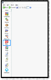

Clicking the Plant icon ![]() in Library will open the Plant Editor as shown above.
in Library will open the Plant Editor as shown above.
Areas of Interest:
1) Plant Details section in the header
2) Spreadsheet section at the bottom of the editor
Plant Details:
This section allows to edit/view the Plant details.
Select Plant: A drop-down menu for selecting a plant present in Assembly Planner.
Description: Displays any descriptions the user defined when creating the plant.
Plant Code: The optional unique identifier the user defined when creating the plant.
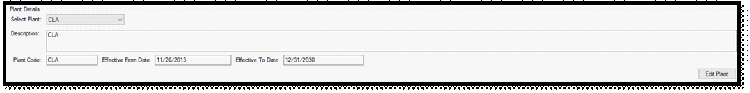
Default From Effectivity Date and Default End Effectivity Date: The default dates if no other dates are chosen when data in other entities (routing, operations, activities, resources, components, etc.) in Assembly Planner is created.
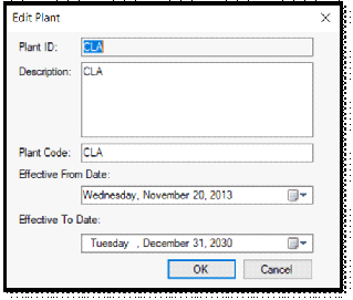
Edit Plant: Allows to edit information about the currently selected plant. Clicking the button brings up the window shown below.
•Description information and Plant Codes can be added, changed, or removed. The default from and end effectivity dates can also be modified. The Plant ID field cannot be edited after the plant has been created.
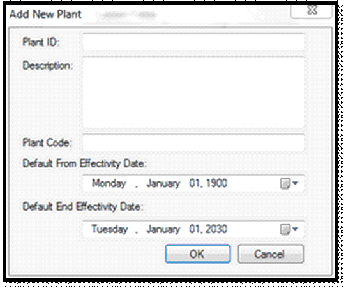
Add Plant: A pop-up window to create new plants in Assembly Planner. Clicking this button brings up this window. You can enter Plant ID, Description, Plant Code, Default Effectivity Dates and press OK. This will add Plants in the application.
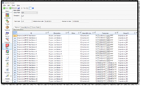
Spreadsheets:
This section allows to add/edit/view Assembly Lines, Stations and their corresponding properties which constitute the different sections of the currently selected Plant.
You can switch between viewing the Station List information, Assembly Lines information and the Custom Fields information by using the tabs at the top of the spreadsheet. And each of fields/columns in either of these tabs have Sorting, Filtering and Customized view (using which columns can be arranged in any order as per user’s requirement) capabilities.
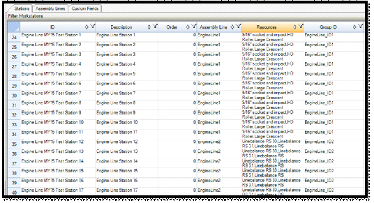
Stations:
If a new work center (station) is added, you must 'Save' and restart Assembly Planner before the new work center will truly exist in the system. Each Assembly Line consists of different stations and all those stations will be defined here. The station created here can be used in almost all parts of the application. For example, in Routing, Line Balance module, Sequence Planner Module, PFEP, etc.
Key Fields:
ID: A unique identifier of the station or work center. This can be copied and pasted from another application or typed manually.
Description: Details or an alternative name of the station or work center. This can be copied and pasted from another application or typed manually.
Order: Change this number to show the order of stations within a plant. It can be utilized while working on a line balance by showing the stations in the sequential order.
Assembly Line: Line to which the station belongs. This is primarily used when publishing electronic work instructions. This field is a drop-down list of Assembly Lines already defined in the Assembly Lines tab.
Resources: Lists resources existing in the station or work center. The Resources column is not something to be filled in until resources have been Imported or added in the Resource Editor.
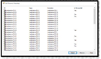
•After resources are available in the system, right-click in the resource cell and select "Edit Resource Mapping". This allows you to assign a resource to a station.
•Simply click the 'Select' button, search for and highlight the resource you wish to add and click 'Add'. If you have multiple resources listed, they will be shown in a comma-separated list when you return to the spreadsheet.
Some resources may need to be considered Monumental for line balancing purposes. See the Resource Editor section for further explanation.
Copy to Shop Floor Viewer: This is a selection of whether a station’s information need to be published for electronic work instructions.
There are many other fields like Image Name, Sector ID, Offset (Days), Offset (Units), Ignore in PFEP, Work Zones, PPE fields, etc. which can be used based on the requirement of the Plant.
Finally, any custom fields created for Stations will also be shown as columns here.
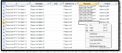
Right-click menu in the Station List Worksheet highlighting the Edit Resource Mappings option

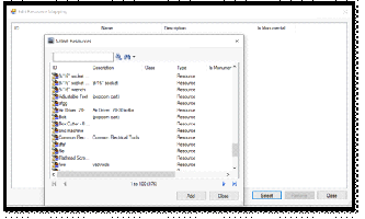
Interfaces to Select Resources to add to Stations
Assembly Lines:
Each Assembly Line within a Plant generally consists of a set of stations. One Assembly Line can feed into another Assembly line at a certain Station. This worksheet helps to add new Assembly Lines and interconnect them with existing Assembly Lines.
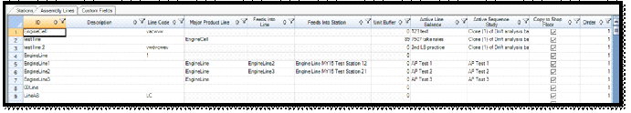
The figure below shows the complete set of fields that help in defining an Assembly Line within a Plant.
If a new Assembly Line is added or an existing Assembly Line property is edited, you must 'Save' and restart Assembly Planner before the changes truly reflect to work in the system. The setup in this tab between the Assembly Lines is very important while working in the Sequence Mass Update Tool. The setup here enables to publish and/or update the corresponding Line Balance Scenarios, Sequence Planner Studies for a set of Assembly Lines interlinked with each other.
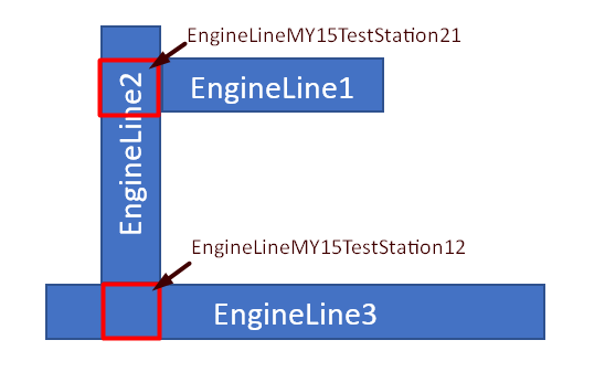
A pictorial representation for Assembly Line setup of manufacturing EngineLine products on EngineLine1, EngineLine2 and EngineLine3 is shown above where ‘EngineLine1’ feeds into ‘EngineLine2’ at station ‘EngineLineMY15TestStation12’ and ‘EngineLine2’ feeds into ‘EngineLine3’ at station ‘EngineLineMY15TestStation21’.
This kind of setup is very useful if you would like to update the sequence planner studies or refresh line balance scenarios of one line dependent on another line in Sequence Mass Update Tool. This tool can be accessed by navigating to Data Mgmt -> Advanced Tools -> Sequence Mass Update tab will be available in Advanced Tools section.
For each of the Assembly Lines that are created here, orders can be loaded, viewed and edited in Order Data Management and in Scheduler modules.
Key Fields:
ID: A unique identifier of an Assembly Line. This can be copied and pasted from another application or typed manually.
Description: Details or an alternative name of the Assembly Line. This can be copied and pasted from another application or typed manually.
Line Code: A unique identifier that helps to associate Units/Orders information with each Line.
Major Product Line: If a line code is defined for an Assembly Line, then the Specific Line is automatically assumed as a Major Product Line. Hence this field cannot be edited once the ‘LineCode’ is specified for an Assembly Line. From above figure, ‘EngineCell’/’EngineLine’ can be considered as examples for a Major Product Line.
•If the Line is not a Major Product Line (i.e., LineCode is not specified), then this field value can be selected from a drop-down list of existing Major Product Lines.
Feeds into Line: This is a drop-down list of the other Assembly Lines which are not Major Product Lines. This field will also be non-editable, if it’s a Major Product Line. Please refer to the below example for more information.
Feeds into Station: This field is a drop-down list of Station IDs that are part of the Assembly Lines that this line will feed into. This field will also be non-editable, if it’s a Major Product Line. Please refer to the below example for more information.
Example:
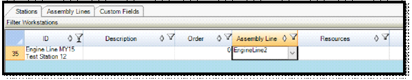
From the above figure, EngineLine1’s and EngineLine2’s Major Product Line is ‘EngineLine’. Hence, EngineLine1 can feed into EngineLine2 or vice versa. Here, EngineLine1 feeds into EngineLine2 at the station ‘Engine Line MY15 Test Station 12’ (which is a station in EngineLine2).
Unit Buffer: Number of units that will wait on the Assembly line before feeding into another Assembly Line.
Active Line Balance: A drop-down list of Line balance scenarios to associate an actively used Line balance scenario with an Assembly Line.
Active Sequence Study: A drop-down list of Sequence Planner studies to associate an actively used Sequence Planner study with an Assembly Line. The corresponding study details can be also be updated using the Sequence Mass Update tool in the application when the study is linked with an Assembly Line. Please refer to the Sequence Mass Update section.
Copy to Shop Floor Viewer: This is a selection of whether an Assembly Line’s information need to be published for electronic work instructions.
Finally, any custom fields created for Assembly Lines will also be shown as columns here.
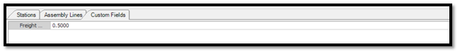
Custom Fields:
The Custom Fields tab shows custom fields that are created for the plant. The values associated to the fields for each of the Plants can be added/updated here. The corresponding properties for each of the fields can be edited in Custom Fields Manager. Please refer to Custom Fields Manager section.