The Shop Floor MES Viewer allows operators and engineers the ability to track parts, file quality issues, and make change requests. Different layouts are explained below:
Layout 1
This Layout displays a variety of process information and allow users to file various roadblocks and alerts as explained below:
Header

The header information is populated based on the following field mapping:
SFV Label |
Assembly Planner Field |
Station |
Operation Work center ID |
Operator |
Activity Operator ID |
Activity# |
Activity ID |
Description |
Activity Description |
Customer |
Unit Customer |
Serial Number |
Unit Serial No |
Final Seat Assy |
Unit Option ID |
Tail# |
Unit Tail Number |
MO# |
Unit MO Number |
AC Install# |
Unit AC Install Number |
Shipset# |
Unit Shipset Number |
CO# |
Unit Order No |
Row Markers: |
Order Data Management Table |
Barcode Report |
Show the barcode for the unit. |
Process tree icon |
Take you on process tree |
Footer
![]()
Time Counter: The first value in the timer section is a counter of the time since the activity was signed on. The second value is the standard time of the activity defined in the activity’s Time field (which is populated by the Estimated Time, Observed Time, or Calculated Time field).
Time Data can be used to generate production reports, giving insight to executing the assembly process. Time Data can also be used to Auto Advance to the next Activity when the Counter reaches the Planned Time
Break-On: this button is used to Pause an Operator's Time Counter for a various production related down time
Sign On Status: displays the status of the Operator-Unit Sign On, is used to clearly indicate an Operator is Signed On to an Activity or if they are in a Preview Only mode
Supporting Documents: documents which are relevant to the process data can be accessed from a link in the footer, documents are commonly published to a file share and are linked to the relevant Activity and can be accessed from the Shop Floor
Change History: provides a history record for changes to the Activity
BluePrints: additional Part Drawing information can be linked and accessed from the Blueprints button
Navigation: using the forward (green) and backward (yellow) buttons, the operator will advance from Activity to Activity, at the time of advancing forward, several validations may take place on the current Activity depending on data setup, the Activity will also be Signed Off in the system as a completed process
The red caution button is used to file a system exception which is explained below, this can include a Part Issue or Quality Issue, and is commonly used to capture reasons why the Activity could not be completed, which is then tracked in the SFV to closure
![]()
Body
Images: If there are images mapped to work steps in the activity, they will appear in the Image Viewer. If there are multiple images, the user can click the arrows above the image to view each one. The work step group to which the current image is mapped will be highlighted, as can be seen in the two screenshots below. The user can also click on the full screen button to display the image in full screen.
Worksteps: The work step information is populated based on the following field mapping:
Work Step Label |
Assembly Planner Field – Work Step Tab |
Grp No |
WorkStepGroup |
Step |
Step No |
Step Description |
Description |
Dimensions: Dimension data can be collected and associated to a work step and activity within SFV. Two fields will be displayed under the work step: Required Dimension and Actual Dimension. The Actual Dimension field is displayed in red until the user enters a value, then the cell color will change to green. Any activity requiring a dimension must have a value entered or roadblock filed to sign off the activity. SFV will except any entered value in the actual dimension field.
The Dimension fields are displayed when the following scenario applies in AP:
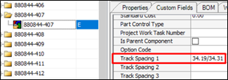
1.In the work step tab, a value is selected from the dropdown list for the “Required Dimension” custom field (Track Spacing 1, Armrest Height, Upright All, etc.)
2.The value is not 0 in the associated Item Custom Field (Track Spacing 1, Armrest Height, Upright All, etc.)
3.The corresponding Item ID is mapped in the Model Option Mapping Tab for the activity

Torque Tools:
If all of the following are true:
•A Resource is mapped to a work step in the Activity Resource tab.
•The Resource has a color defined in the Resource’s “Resource Color” field.
•A part is mapped to a work step in the Activity Consumption tab’s “Work Step No” field.
•That part’s defined Torque value in the Activity Consumption tab’s “Torque” field falls within the Resource’s “MinTorque” and “MaxTorque” range.
•That part’s “Is Torque Required” field is set to true (check box checked) in the Activity Consumption tab.
Then:
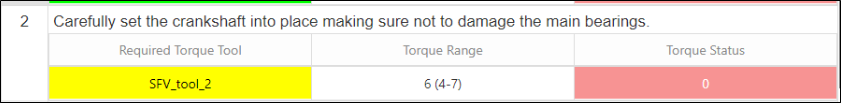
•The Resource will appear underneath the work step under the label “Required Torque Tool”.
•The Resource will be highlighted with its defined color.
•The associated part will be highlighted with the Resource’s defined color in the Parts table.
•The user will be required to type in a Torque value into the Torque Status cell that appears next to each Required Torque Tool. This cell will be highlighted in red if no value has been entered or if the entered value does not fall within the Resource’s MinTorque and MaxTorque. If the entered value does fall in the correct range, the cell will be highlighted in Green.
Parts Table:
Parts Label |
Assembly Planner Field – Activity Consumption Tab |
Ref |
Ref |
Part Number |
Part ID |
Qty |
Qty |
Part Description |
Part Description |
Part # Aggregation:
Part Numbers will be aggregated in this table, by displaying the part only once and showing the total summed quantity if:
•Part ID is mapped to more than 1 work step within a work step group.
•Part ID belongs to the same Option Item in each instance.
•Part ID is assigned to same torque color in each instance.
Part Serial Numbers: If the “Is Serial No. Req” field is set to true (checked) for a part in the Activity’s Consumption tab, a Serial # entry (or multiple, depending on the Qty) will be displayed underneath that part.
Part Hyperlink: In the Component Editor, if the “Hyperlink” field is populated for a part, the part number should appear as a hyperlink, and the link should open the PDF defined in that field.
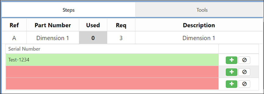
Each Serial # entry box will be highlighted in red until a user inputs a serial number. Then the cell will be highlighted in green. The user will not be able to advance to the next activity unless all required serial numbers have been input, or the appropriate Part Exception Road Blocks have been filed. Please see the Part Exception section for more details.
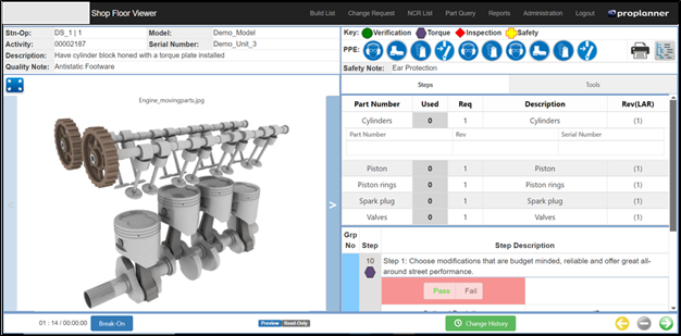
Layout 2
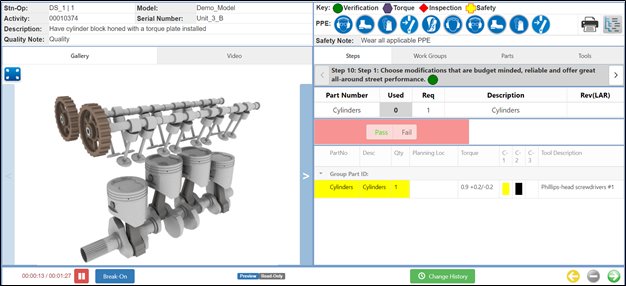
Layout 2 display one Work step at a time. Colors are defined for parts and torques.
Header
The header information is populated based on the following field mapping:
SFV Label |
Assembly Planner Field |
Stn-op |
Operation work center id – activity operator ID |
Activity |
Activity ID |
Description |
Activity description |
Quality Note |
Activity Quality note |
Key |
Display all keys |
PPE |
PPE fields from Activity |
Safety Note |
Activity Safety note |
Barcode Report |
Show the barcode for unit |
Process tree icon |
Take you on process tree. |
Part color:
To associate color with a part you need to associate part with an option and then assign option a color. You can specify both text and background color in list management color list.
Resource color:
A resource is assigned a torque value. The torque value then can be linked to colors in list management. We support three Colors per torque value.
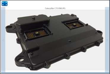
Image & Video tab:
User can associate maximum one image per workstep and a video per activity.
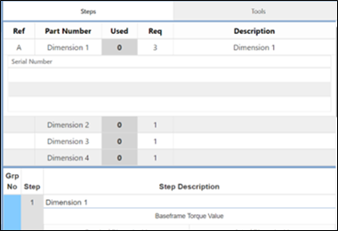
Steps and work groups Tab:
Display information based on Workstep tab in assembly planner. You can click on a workstep in group tab to navigate.
Parts and Tools tab:
Display an aggregated list of all parts and tools used in an activity.
Timer:
The auto advance timer can be set for both activity and workstep. To set the default time the preference exists in database:
![]()
Timer is disabled when a popup is opened and restarts on new workstep\activity. Timer can also be paused and started manually.
Break-on:
SFV gives user an ability to record breaks and display reports. The list of break types can be customized from database.
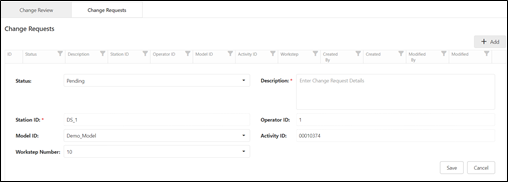
Change history:
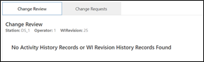
SFV gives an overview of all changes requested and implemented in this tab. Changes can be published per activity and per WIRev basis. These changes will need to be acknowledged by users based on preferences.
Users can file requests directly from WI page using requests tab.
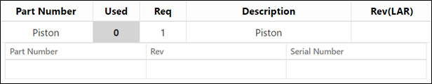
Part tracking:
Part tracking can be enabled for users using this preference on TC database:
![]()
You can track part Rev, Serial number and Qty.
WI tests:
Different test types available for users are:
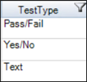
User can enable soft failures which will allow operators to advance even when the result doesn’t match with specified result. By unchecking the checkbox “Required in spec” in WI tab.
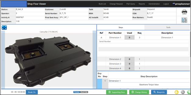
Layout 3:
The layout 3 is very similar to layout 2 except the fact that layout 3 displays all parts and work steps available in activity steps on the same page. The tabs are reduced to work step and tools. No colors are defined in this layout.